Computed Tomography for Materials Science and Life Science
by Dr. Cameron Chai and Richard Trett
A modified version of this article was published in Materials Australia magazine– September 2016
Computed Tomography or CT is a non-destructive imaging modality that provides much more than just non-destructive testing (NDT) of materials and components. Using CT, highly detailed 2D and 3D images of components can be generated that provide valuable insights into their inner structures. CT can reveal such things as density, voids, pores, cracks, inclusions and other internal defects that have the potential to lead to premature or catastrophic failure in service. Better still the 3D data is quantifiable and can be used with mathematical and structural models to conduct finite element analysis for example or as a metrological tool.
Evolution of Materials Testing from Medical Technology
Computed Tomography (CT) or CAT scanners were originally developed by the British engineer Godfrey Hounsfield and South African Physicist Allan Cormack in 1972 for medical applications. Their work earned them a Nobel Prize in 1979. CT scanners have been used in clinical applications since the mid 1970s to non-invasively provide detailed images of the inner workings of human bodies.
The same technology has also been applied in NDT for the last 30 years. The earliest systems were modified medical systems. Systems suitable for materials analysis are now commonplace with specifically designed systems also available, e.g. wheel inspection systems.
Computed Tomography in Materials Testing and Manufacturing
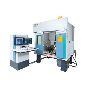
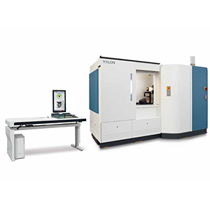
 In the materials industry, CT systems like this manufactured by YXLON are commonly used as a rapid quality control check for critical components particularly where 100% inspection is required for such things as critical aircraft or automotive components, lifting hooks, wheels etc. In these applications it can identify defects beneath the surface that are invisible to external inspection techniques. In other applications, it can be used on a batch basis. It is also used for failure investigations or process control and optimisation.
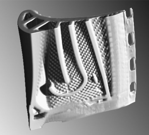
It is also useful for looking non-destructively inside composite structures. With materials such as fibre reinforced plastics (GFRP) and even carbon fibre reinforced plastics (CFRP), CT can be used to look at fibre stacking and orientation, as well as porosity.
Computed Tomography for Research
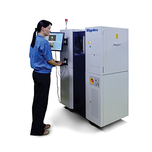
CT is also a favoured tool for research applications. Systems like the Rigaku nano3DX are excellent as they can be used to non-destructively inspect systems. This allows them to be tested again down the track or used for other experiments.
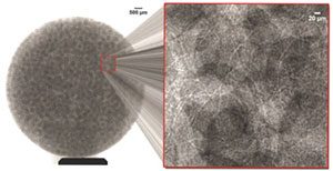
The nano3DX is suited to life science offering high resolution and high contrast imaging. CT can be used to evaluate the osseointegration of orthopaedic implants in preclinical trials. In this application, the progress of a single subject could be monitored, rather than using a series of animals that would be sacrificed at various time intervals.
Computed Tomography in Pharmaceuticals
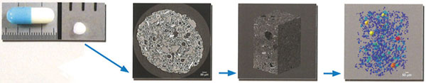
 CT can also be used to examine tablets and pharmaceuticals. In this application, it can be used to reveal such things as:
- Packing density and porosity
- Packing distribution or various components
- Uniformity of layers and/or coatings
CT Components and Configuration
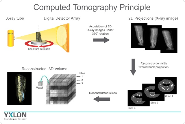
CT systems are similar in nature and configuration to human systems. The specimen is located between an X-ray source and an X-ray detector. Depending on the system, the X-ray optics will revolve around the sample or the sample will rotate on a turntable between stationary optics to create the same overall effect.
Industrial systems are also typically enclosed in housings to prevent exposure of operators to stray X-rays. Well-designed enclosures allow easy access to the sample stage which is of particular importance for inspection of large and heavy components. It is also possible to automate the inspection process even to the extent of being included on a production line for automated defect detection.
Systems may also be configured specifically to inspect the microstructure of materials. Typically referred to as microCT or X-ray microscopy, these systems operate on much smaller samples. With the aid of much higher resolution detectors and/or microfocus x-ray sources they can generate data sets with sub-micron resolution.
How Does Computed Tomography Work?
As X-rays pass through the specimen, differences in density and structure result in alterations to the absorption of the X-rays. The transmitted x-rays strike a scintillator, a material that converts the X-rays into visible light. The visible light can then be detected in a variety of detectors including CCD and CMOS detectors for example. The X-ray images are effectively absorption contrast images and produce a projection image similar to that of a medical X-ray. Detectors can be area detectors or linear detectors. We will discuss area detectors that are used in what is referred to as cone beam CT.
CT requires a large number of these absorption images to be collected at known angles typically over 360 degrees around a sample. These images can then be used in a reconstruction technique that is termed back projection. The path of the x-ray is traced back from the detector to the source providing the average density (absorption) over this x-ray path. This back projected path is collected for each point on the detector for every single image.
Combining the back projected data from many hundreds or even thousands of images, the data is reconstructed in what is an extremely computationally heavy process. It has only been in the last decade that this process has occurred in a reasonable timeframe on commercially available computers. However CTs typically employ multiple state-of-the-art GPUs to process data in short timeframes.
 Resolution and Voxels
With 2D digital graphics, we often refer to their dimensions in terms of pixels, with a pixel being the smallest single definable element. With 3D computer generated renderings, the smallest element is a voxel, which can be likened to a 3D pixel, or a combination between volume and pixel.
In industrial systems for larger parts, a typical voxel size of 50µm to 200µm and can be used on items like automotive gearboxes. Micro CT voxel sizes as low as 250nm can be achieved but on smaller samples in the range of pharmaceutical tablets, but a series of images can be stitched together effectively providing analysis of larger objects.
These higher resolutions require high magnifications and the X-ray source typically very close (as close as possible) to the sample.
Software
Modern CT systems incorporate powerful software packages and user-friendly graphical user interfaces. These automate many operations and make sophisticated systems easy to use.
Perhaps the most significant aspect to the software is the analytical power that it brings to your disposal. Apart from being able to create 3D reconstructions and from these individual cross-sections or slices, it also allows you to zoom in on sections and effectively deconstruct the component to see details that would only be available by cutting open the sample.
The software also gives you metrology capabilities allowing you to take measurements that can be compared to CAD drawings to check dimensional accuracy. It also enables you to compare parts from the same production line or from other manufacturers or production lines to gauge consistency. At the other end of the scale, they can also be used for reverse engineering.
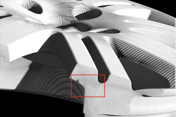
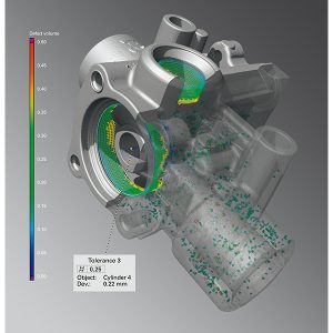
CT is particularly useful for complex internal or undercut features where it can be difficult or impossible to examine with conventional x-ray. It gives you the ability to accurately measure the size of voids and pores and other internal, sub-surface defects.
Data sets can be combined with other mathematical software to model failure or mechanical testing with FEA for example. It is common practice to use porosity data to model flow through porous structures in CT software.
Applications
As mentioned, CT can be used as a QC tool to non-destructively check the quality of weld joins, tolerances of manufactured parts or detect pores, voids and other manufacturing defects. It is particularly useful for checking complex structures where computer models can provide access to hollow or internal surfaces that may be difficult to access and impossible to check dimensional accuracy using more conventional methods.
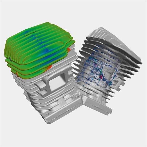
It can also be used for process refinement and prototyping e.g. for cast components. In this type of application, material flow into certain areas of the mould may be difficult or incomplete. By examining the structure of the component, voids may be found and provide insights into how the process or mould design can be improved to produce better results.
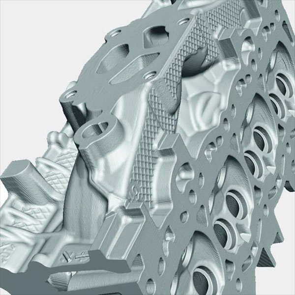
CT is suitable for the analysis of all manner of materials from metals to ceramics and polymers as well as composites where individual fibres can be resolved. It can also be used on assemblies e.g. whole car engines and electronics that may include any number of individual parts made from differing materials.
It has also been used to look into cultural assets and artefacts. In this application, researchers can see inside delicate treasures such as statues without the need to open them up. This provides a better understanding of how they were made which can be very revealing prior to restoration.
Summary
CT is a technology that was originally developed for medical applications that is now well entrenched into the materials industry. It enables users to non-destructively see deep inside their components or assemblies. Using computer generated images, any part or region can be examined in detail. This technology is especially relevant to economies like Australia which are suited to manufacturing high end components where it can be used in process optimisation and quality control.